Ats Diagram 3 Wire Pump Pressure Control

In which i control a three phase submersible pump motor using magnetic contactor.
Ats diagram 3 wire pump pressure control. 2 wire submersible well pump wiring diagram a newbie s overview of circuit diagrams. It is not a 3 ph pump it s a 3 wire system that utilizes a control box to house the capacitors and relay rather than having them in the submersible pump itself. The franklin suggestion was good they do have diagrams of their control boxes and it does appear that the incoming wire need only be 8 2. 3 phase submersible pump wiring diagram.
Manifold pressure switch cp3 pump installation wiring diagram revised 5 19 06 fass pump red wire green wire ground optional switch for manual control over on off operation 87 86 85 87a 12 volt source key on 12 volt source full time recommend attaching to jump start post not used supplied wiring harness relay ground wide open throttle switch. Not only a contactor but also i install the thermal overload relay which will protect the motor form burning in case of over current flow to the circuit. Pressure sensor wiring diagram duration. Here is the complete guide step by step.
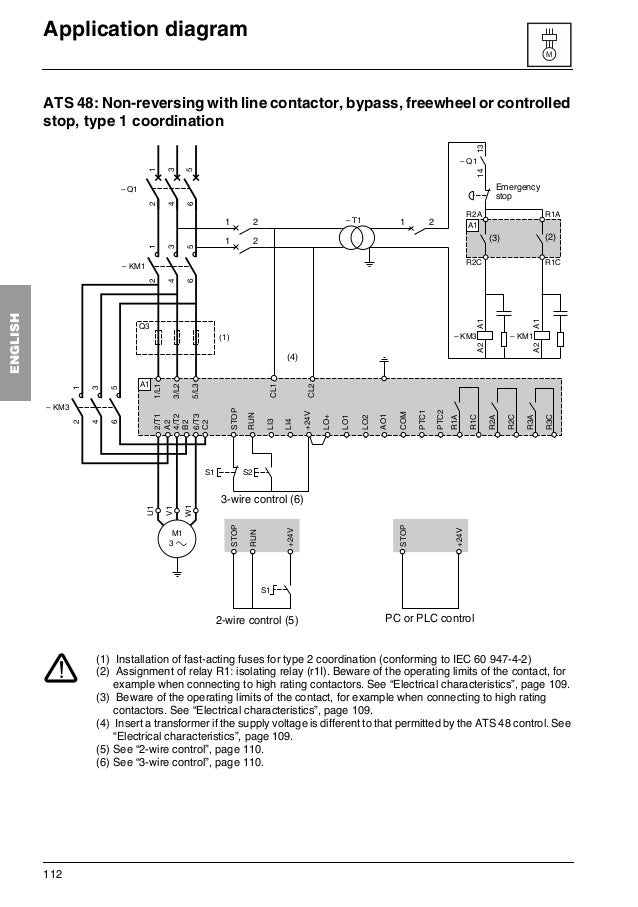
See image below for an example of 3 wire control being used to pull in a contactor to start a 3 phase motor. Installation of auto water pump controller aqua starter. Manufacturer of submersible pump control panel three phase submersible pump control panel ats 10 hp dol starter control panel 20 hp single phase submersible pump control panel and v4 submersible pump control panel offered by kaizen electricals ahmedabad gujarat. Single phase submersible pump control box wiring diagram 3 wire submersible pump wiring diagram in submersible pump control box we use a capacitor a resit able thermal overload and dpst switch double pole single throw.
A very first look at a circuit layout could be complicated however if you can review a subway map you could read schematics. 3 wire well pump wiring diagram. 3 wire well pump wiring diagram entitled as wiring diagram for well pump pressure switch best water well control 3 wire well pump wiring diagram also describes wiring diagram for well pump pressure switch best water well control and labeled as. 3 way wire connector 3 wire color code 3 wire fan 3 wire ignition coil diagram 3 wire rtd theory with resolution 1584px x 1584px.
Control wiring 3 wire control start stop circuit the most common use of 3 wire control is a start stop control.


